Abstract. Despite much research and discussion on the subject of reflow profiling, many questions and a good deal of confusion still exist. What is clear is that the pains often associated with profiling can be reduced if there is a strong understanding of the variables that can be encountered during the reflow process, as well as the metallurgical dynamics of the soldering process. This paper shall provide a brief outline of the reflow profile in general, with specific emphasis placed upon the suggested time spent above the melting temperature of the solder. The guidelines for soldering to various surfaces and with alternative solder alloys also are discussed.
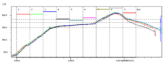
General Reflow Guidelines. While varying reflow profiles may be utilized to achieve optimum soldering results, in general these share many of the same details. For the Sn63/Pb37 and Sn62/Pb36/Ag2 alloys, the typical profile length is 3 ½ to 4 minutes from the time the assembly begins to heat up until it reaches its maximum temperature of 215°C ± 10°C. The assembly is reflowed above the liquidus point of the solder (183°C for Sn63, 179°C for Sn62) for a target time of 60 seconds ± 15 seconds. It should be noted that this time above liquidus is measured not only during the profile’s rise, but also during its cool-down. The cool down rate of the profile should be controlled within 4°C per second. In general, a faster cool down rate will result in a finer grain structure and a stronger and shinier solder joint. However, exceeding 4°C per second could result in thermal shock to the assembly.
Reflow Dynamics- Intermetallics. The goal of the soldering process is to form an intermetallic layer between the solder and the circuit board and the solder and the component. Simply explained, an intermetallic is a combination of the base metals with the solder that provides the mechanical and electrical integrity of the solder joint. However, as most frequently used in soldering, the term “intermetallic” is often used as an abbreviation for intermetallic crystal (IMC), which refers to a specific class of materials. As discussed below, it should be noted that IMCs are a problem of soldering and can lead to long-term failures.1
When soldering to a copper substrate with tin/lead solder, two types of IMCs are formed. The copper-rich Cu3Sn intermetallic, which melts at 670°C, is found near the substrate, while the tin-rich Cu6Sn5, which melts at 415°C, is found throughout the joint. As the melting temperatures of these are significantly higher than soldering temperatures, they will not be melted during the reflow process and thus will remain in the joint as occlusions. During soldering, the intermetallic crystals are precipitated out. This intermetallic will continue to form at a slower rate in the solid phase. The growth as a solid is driven by temperature; as the solder approaches its melting point, the rate of intermetallic growth increases. Most growth does not amount to much below 125°C, but at 150°C the intermetallic growth is logarithmic to the temperature increase. It is for this reason that high-tin Sn/Pb systems should not be utilized to assemble that devices that operate above 150°C for extended times and that it is recommended to stay below 250°C during soldering. The dissolution rate of copper at various temperatures is shown in the chart below.
| Temperature °C | Dissolution rate um/s | Dissolution rate nim./s |
| 250 | .47 | 18.5 |
| 275 | .70 | 27.6 |
| 300 | .88 | 34.6 |
| 350 | 1.10 | 43.3 |
To prevent the reactions between solder and copper, a layer of less-reactive metal can be used as a barrier. Nickel is used extensively for this purpose as a barrier plating, as there is very little formation of intermetallic compounds during the tin-lead soldering process. Iron also is used, albeit far less extensively, for this purpose.
Time above Liquidus and Delta T. The goal of achieving the target time above liquidus is to achieve optimal solder spread on solder joints across the circuit board. Other benefits are to reduce flux entrapment and voiding and increase pull strength. Generally, solder liquidus times of 30 to 60 seconds are preferable, although liquidus times of 90 seconds or more are not uncommon on larger boards. This is due to the potential of a large Delta T of an assembly with a large variation of thermal mass. Delta T is defined as the greatest difference of temperature found across a circuit board. The result of a large Delta T is that some areas of an assembly heated could reach much higher temperatures than other areas. Therefore, in order to ensure that all parts of an assembly reach the minimum requirements of time above liquidus (i.e., 30 seconds), the more rapidly heated areas may be exposed to the upper limits (90 seconds) of time above liquidus.
Solder Spread & Wetting Angle. The solder spread and wetting angle of a solder joint are the most pertinent visual inspection criterion for a properly reflowed assembly. Greater solder spread and a lower solder joint angle are indicative of a properly reflowed, and therefore more durable, solder joint. In general, a solder joint angle of 75° or less is desirable. Ideally, the solder is feathered out, indicating a small dihedral angle. In addition, the solder joint will appear bright and smooth, with few or no pinholes.
As discussed above, the time above liquidus necessary to achieve adequate wetting appears to be in the range of 45 to 90 seconds. If the solder is above the reflow temperature for too short a time, there is the risk that marginal or non-wetting will occur, which will have a deleterious effect upon solder joint reliability. In pull tests, solder joints exposed to lower times above liquidus tend to have higher failure rates.
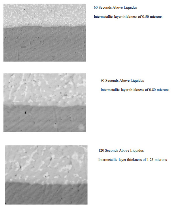
Excessive Time Above Liquidus. Reliability-related issues also can occur if the solder is above reflow temperature for too long a time. During the soldering operation the molten solder will dissolve the metallization and/or the base contact metal and precipitate intermetallics that will form the bond responsible for giving the solder joint its strength. If the metallization dissolves too rapidly or is too thick the integrity of the solder joint can be compromised by forming too large a volume fraction of the intermetallic phase. Once a joint develops a coherent layer of intermetallic compounds, it loses its metallic properties and becomes brittle, and any subsequent shock or stress to the joint can lead to failure2.
In a comparative test, solder joints were reflowed for 60, 90 and 120 seconds above liquidus. As is shown below, the intermettalic layer increased significantly with each incremental increase in time above liquidus.
Peak Temperature. In addition to time above liquidus, the minimum peak temperature reached during the soldering process is also vital. For example, when soldering a copper substrate with Sn63/Pb37, the peak temperature is generally in the range of 205° to 215°C. Too high of a reflow peak temperature can lead to excessive copper dissolution and intermetallic formation and damage to the flux vehicle. It should also be noted that flux damage can occur if certain temperatures are exceeded during the reflow process. As all fluxes contain organic acids or esters of acids, these compounds normally begin to decompose around 150°C. Some other organic acids such rosin will be active up into the mid-200°C range. As the decomposition of these materials begins, their soldering ability rapidly degrades. Typically, to achieve the best wetting, a short profile with a peak temperature less than 240°C is ideal. This limits the amount of out-gassing as well as the amount of copper that is dissolved into the system. The duration of this profile should not exceed 3 minutes above 150°C and should be 60 ± 15 seconds above 183°C.
Soldering to Other Substrates and/or With Other Alloys. The surface tension of the solder alloy in use and the intermetallic growth rates of the solder and base materials are two critical factors to consider when soldering to other substrates and/or with other solder alloys. In regards to surface tension, during soldering the surface temperature of the solder must reach a low enough level to allow for adequate spreading. It is well-documented that certain alloys, such as the tin-silver-copper family of lead-free alloys, do not require as great a temperature above liquidus to achieve adequate soldering as does Sn63/Pb37. For example, when soldering with a tin-silvercopper alloy, a commonly recommended and utilized peak temperature is 240°C, which is 22°C above the alloy’s melting temperature, whereas the typical peak temperature when soldering with Sn63/Pb37 is 32°C. In general, the surface tension of tin/lead alloys is more dependent upon temperature than other common solder alloys.
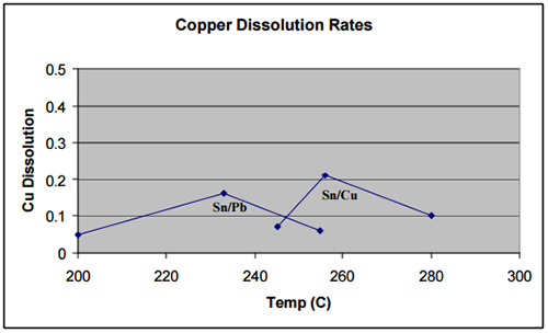
In regards to the intermetallic growth rates of solder and base materials, it should be noted that different alloys develop intermetallics with different base materials at varying rates. As an example, lead-free high-tin alloys generally show higher dissolution rates with most metals as compared to tin/lead. However, exceptions exist where the lead-free alloy already contains a percentage of the base metal, such as silver or copper, in which cases the dissolution rates are similar to those of tin/lead. For instance, as the graph below demonstrates, rates for copper dissolution in Sn99.3/Cu0.7 were found to be slower than tin/lead.3
As an aside, relatively rapid intermetallic growth can occur over time when exposed to constant high temperature. (Although this will also occur even room temperature, these growth rates are generally so low as to not affect a device during its field service). As the graphs below demonstrate, alloys that already contain a percentage of the base metal generally better inhibit intermetallic growth over long periods of time when exposed to constant high-temperature.4 This inhibition can translate to superior long-term reliability of devices that are exposed to constant high-temperatures.
Soldering to Gold/Nickel. As gold-over-nickel (Au/Ni) coated circuit boards are becoming increasingly prevalent, it is worth discussing the particular soldering guidelines and requirements when soldering to this material. When eutectic tin/lead solder is reflowed in contact with the Au/Ni metallization layer, the Au quickly (1mm/sec) dissolves into the solder and forms a distribution of AuSn4, a long, brittle structure, throughout the solder. If the gold concentrations in tin-lead solder reach too high a level, embrittlement of the solder joint will occur, which can lead to a significant reduction in the fatigue life of the solder joints. It is commonly accepted that gold embrittlement will not occur with less than 3% gold.5 One way to reduce this problem is by keeping the gold thickness to a minimum.
In situations where thick Au deposits (>20 m-inches) are present, the large quantity of AuSn4 that forms usually segregates and cannot disperse uniformly through the solder connection. The elevated concentrations of Au in the areas of segregation greatly degrade the integrity of the solder connections, especially where cyclic thermal environments are encountered in service.
Recent research also has shown that after aging at 150 °C for as little as 3 hours a new ternary compound with the nominal composition of Au0.5Ni0.5Sn4 can grow on the solder side of the Ni3Sn4 intermetallic layer. The aged joints were found to be significantly weaker than the same joints tested before aging.6
When soldering to gold surfaces it is important to fully dissolve the surface into the solder to prevent long-term failure from occurring due to solid state diffusion of the gold into the solder. Solid state diffusion (scavenging) occurs when a gold surface has been left in contact with tin. Over time and temperature the gold will dissolve into the solder, leaving a void that causes the solder joint to fracture. If lead is present, the intermetallics that are formed from gold and tin will embrittle the solder joint. This is due to the precipitation of the gold intermetallic along the lead grain boundaries forming intermetallic crystals. To prevent this occurrence, it is important to exceed 217°C when making solder connections to gold. Looking at the gold-tin phase diagram, this is the point that a secondary gold-tin eutectic forms, and exceeding this temperature will fully dissolve the gold into the tin. To ensure that this temperature is surpassed and proper flow and wetting are achieved, a 220°C reflow profile is recommended.
Soldering with high-tin alloys (such as lead-free solders) also can help to reduce the problems related to gold surfaces. These alloys totally dissolve the solder into the gold and then disperse the gold evenly through the joint, therefore the formed intermetallics are not an issue and sometimes act to strengthen the joint.
Conclusion. Time and temperature above liquidus during the reflow process is a critical factor in ensuring a properly soldered assembly. Of special importance is the total time spent above the liquidus of the solder being utilized. If too little or much time is spent above the liquidus point, the reliability of the soldered assembly is jeopardized. By following the guidelines presented in this paper, the integrity of solder joints and, thus, the reliability of devices, can be increased. As always, this application material is presented as general information only, with the optimum assembly process set points dependent upon the unique parts and assembly equipment being used during the manufacturing process.
ACKNOWLEDGEMENTS
Special thanks to Jeff Stong of the American Competitiveness Institute in Philadelphia, Pennsylvania USA for the preparation of the intermetallic images.
1 Manko, Howard. Solder and Soldering. Third Edition, 1992, McGraw Hill. p. 98
2 Manko 101
3 Testing performed by the International Tin Research Institute, United Kingdom.
4 Testing performed by the International Tin Research Institute, United Kingdom.
5 Glazer et al. Proceeding of the Technical Program, Surface Mount International Conference & Exhibition, August 1991, p. 629-639.
6 Minor, A.M. and J.W. Morris, Jr., “Growth of a Au-Ni-Sn Intermetallic Compound on the Solder Substrate Interface After Aging”, Metall and Mat Trans.
Written By David Suraski, Executive Vice President
Download:


