Contents:
Additional applications information, such as reflow profiling, eliminating voiding, tombstoning & solder beading, bar solder drossing and flux conformal coating compatibility can be found in AIM's numerous Technical Articles: Read Technical Articles
_______________________________________
Screen Printing Process
Screen printing is the first, and arguably the most, critical step in processing surface mount technology today. Below are some simple set-up and process recommendations for developing or critiquing your printing process. Most printers, whether they are totally manual or fully automated, will have some form of adjustment for the following.
Many of the problems associated with the printing, component placement, and reflowing of solder paste are due to the improper methods by which solder paste is handled and applied. In addition, the environmental conditions in which the paste is printed and reflowed is critical to the performance of solder paste. By following a few simple handling and application procedures, solder paste defects may be reduced greatly or eliminated.
_______________________________________________________
Snap Off
Recommendation
0.00", ( on-contact )
Definition
Distance, or gap between the top side of the substrate to be printed, and the bottom side of the screen or stencil. Snap-off is used for two basic reasons, to help facilitate the release of solder paste from stencil aperture openings, and to help print a heavier deposition of paste onto the substrate.
How it works
During the print cycle, pressure exerted by the squeegee blade forces the screen / stencil down onto the substrate to seal the immediate area being printed. As the squeegee blade passes, the screen / stencil returns to the original pre-set "snap-off" distance, theoretically peeling itself away from the solder paste, leaving it on the printed substrate.
Drawbacks of snap-off printing
Snap-off is a carry over from the days of printing through screens. It may prove to be a viable alternative to facilitate the use of a poorly cut stencil and may still be necessary for specific equipment or applications; however, it is not necessarily a repeatable process and will not work in every case.
The use of snap-off eliminates any 'gasketing' effect, (sealing of the printable pad area by the stencil ), desired for finer pitch applications. This can cause solder paste to 'bleed out' or spread underneath the stencil during the printing cycle, causing a continuous bridge of solder paste over what used to be individual component pads.
The use of snap-off can also cause peaking in the solder paste deposit, poor uniformity in paste deposition, and inconsistent printing results.
Benefits of on-contact printing
The key benefits of on-contact printing are simple. This process allows a full 'gasketing' of component pads during the print cycle, which will prevent 'bleed out' and bridging, even on UFP components.
On contact printing also provides for a more uniform solder paste deposition and more consistent paste height.
Adjustment
To establish 0.00" snap-off, (on contact) printing, perform the following steps:
- Select a good flat substrate.
- Position the substrate to be printed under the stencil.
- Lower the stencil, or raise the board to the print height.
- Remove all vacuum holding the board by turning it off, closing of vacuum gates is not sufficient.
- Adjust stencil snap-off so that there is a definite gap between the bottom of the stencil and the substrate surface across the entire substrate surface.
- Using your finger, deflect the stencil surface down toward substrate, lowering the snap-off distance slowly until the stencil just makes contact with the substrate surface across the entire printable area.
- For manual printers, lock the stencil height into place and reset dial indicators to 0.00", for automated printers, record the new snap-off distance, save changes and repeat steps 2, 3, & 6 to verify adjustment.
Note
It is important to be aware that on some computer controlled equipment, simply setting the snap-off distance found in the set-up menu is not enough. The snap-off distance in these machines is dependent upon how the calibration of the axis controlling snap-off is performed. Always verify your adjustments.
When adjusting snap-off, remember to continuously check the entire board area. Often the outer edges of the board will make contact with the stencil before the printable area does. If this occurs, verify board support or nesting, or verify that the board you are using is not warped. The concern is that it is possible to end up with too much downward stencil pressure which will create a false and inconsistent snap-off.
_______________________________________________________
Separation Distance
Recommendation
0.010" to 0.050" - Dependent on board thickness, snap-off and downstop settings.
Definition
Distance Z-tower or board support will lower at a controlled speed to clear stencil before proceeding to its home position.
How it works
Separation distance is a feature designed to aid the separation of solder paste from the stencil apertures. Some board supports vibrate as they lower ( this is a result of a stepper or servo motors slow rotation speed ), which also helps the solder paste to release.
After the print cycle has completed, the Z-tower holding the newly printed substrate will lower at a pre-specified speed ( usually low, medium, or high ), to a previously set separation distance. Once this distance has been reached, the Z-tower will lower at full speed to it's home position.
Drawbacks of Separation Distance
The biggest drawback of using separation distance is that it will slow down the overall print cycle time. This will hardly be noticable at the smaller settings; however when approaching higher limits, a dramatic increase will be noticed.
Benefits of Separation Distance
The key benefits of using separation distance is that it will almost always promote better solder paste release from stencil apertures. It will also promote more uniform solder paste deposits and will minimize peaking.
Adjustment
To establish an optimum separation distance, begin by adjusting the separation distance in the set-up menu to 5 mils thicker than the stencil material being used, then execute the following steps. For example: if the current stencil thickness is 0.006", then the starting separation distance should be 0.011".
- Select a good flat substrate.
- Position the substrate to be printed under the stencil.
- Lower the stencil, or raise the board to the print height.
- Remove all vacuum holding the board by turning it off, closing of vacuum gates is not sufficient.
- Adjust stencil snap-off so that there is a definite gap between the bottom of the stencil and the substrate surface across the entire substrate surface.
- Using your finger, deflect the stencil surface down toward substrate, lowering the snap-off distance slowly until the stencil just makes contact with the substrate surface across the entire printable area.
- For manual printers, lock the stencil height into place and reset dial indicators to 0.00", for automated printers, record the new snap-off distance, save changes and repeat steps 2, 3, & 6 to verify adjustment.
Note
It is important to be aware that on some computer controlled equipment, simply setting the snap-off distance found in the set-up menu is not enough. The snap-off distance in these machines is dependent upon how the calibration of the axis controlling snap-off is performed. Always verify your adjustments.
When adjusting snap-off, remember to continuously check the entire board area. Often the outer edges of the board will make contact with the stencil before the printable area does. If this occurs, verify board support or nesting, or verify that the board you are using is not warped. The concern is that it is possible to end up with too much downward stencil pressure which will create a false and inconsistent snap-off.
_______________________________________________________
Print Speed
Recommendation
Less than 1 to 12 inches per second (dependent on formulation and viscosity)
Definition
Print Speed, also known as squeegee cycle speed, is the traverse or travel speed of the squeegee assembly during the print cycle.
How it works
Print speed works in conjunction with many other parameters, including squeegee pressure, squeegee material type, paste chemistry or viscosity, stencil aperture opening size and orientation, etc. For example, to run a high viscosity solder paste at a higher print speed, it is usually necessary to increase the squeegee pressure in order to obtain a good clean wipe of the stencil surface during the print cycle.
Drawbacks of high-speed printing
It is important to understand how your solder paste chemistry reacts to varying print speeds. Solder pastes experience a phenomenon known as shear thinning. Shear thinning may be confused with slump, but the cause is entirely different. Shear thinning is caused by a temperature increase at the point where the squeegee material meets the stencil. This rise in heat level is a direct result of the higher squeegee cycle speeds and increased squeegee pressure necessary to perform high speed printing. The biggest difference between a solder paste affected by slump and one affected by shear thinning is that once the print cycle has stopped, a good rheology paste will typically regain its robustness once shear thinned. Slump, on the other hand, is a sort of melt-down of the solder paste rheology caused by elevated temperatures and/or a low metal load or low viscosity chemistry.
Defects normally caused by high speed printing range from insufficient pad coverage to pad-to-pad shorting. Insufficient pad coverage in high speed printing is commonly caused by either having the incorrect paste formula or viscosity selection or too fine of a stencil aperture opening. Pad-to-pad shorting normally is the result of shear thinning. In either case, at high squeegee speeds, solder paste does not have enough time to properly fill stencil apertures before the squeegee passes, leaving less of a deposit on the component pad, and often an insufficient solder or open defect post reflow.
In addition, the extra pressure and speeds settings required for high speed printing take a toll on transducers, servo motors, squeegee blades and stencil life, and typically require more maintenance than normal.
Benefits of high-speed printing: Throughput.
Adjustment
High speed printing generally refers to print speeds between 4 to 8 inches per second. When in doubt, contact us for more information regarding your specific application.
Note
Ideally, print speeds should be adjusted to just fast enough so that the printer is not slowing up the rest of your line. There is no benefit to printing high speed unless there is no other alternative for your process. As a rule of thumb, there is no benefit to printing high speed unless there is no other alternative for your process. When setting up a high speed printing process, adjust print cycles to an on demand cycle rate, where the printer is "waiting" as short a time as possible between print cycles. This will allow you to optimize print cycle times and will allow your solder paste to maintain a more stable rheology.
If you have no other choice but to print high speeds, you should make sure to utilize a solder paste designed to withstand this process. It is also necessary to provide better, more thorough board support for the product being printed. When in doubt, contact us for more information regarding your specific application.
_______________________________________________________
Squeegee Pressure
Recommendation
1 to 1.5 lbs of pressure per linear inch of squeegee blade is typical. See adjustment below.
Definition
Downward pressure, measured in PSI, (pounds per square inch), exerted by the squeegee blade onto the stencil surface during the print cycle.
How it works
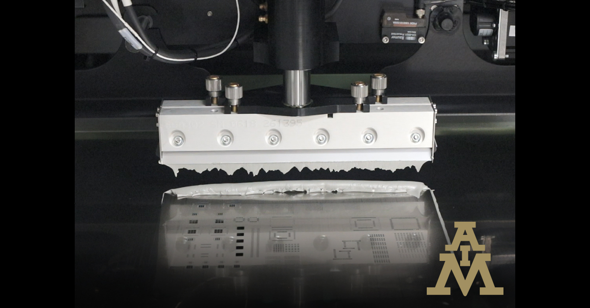
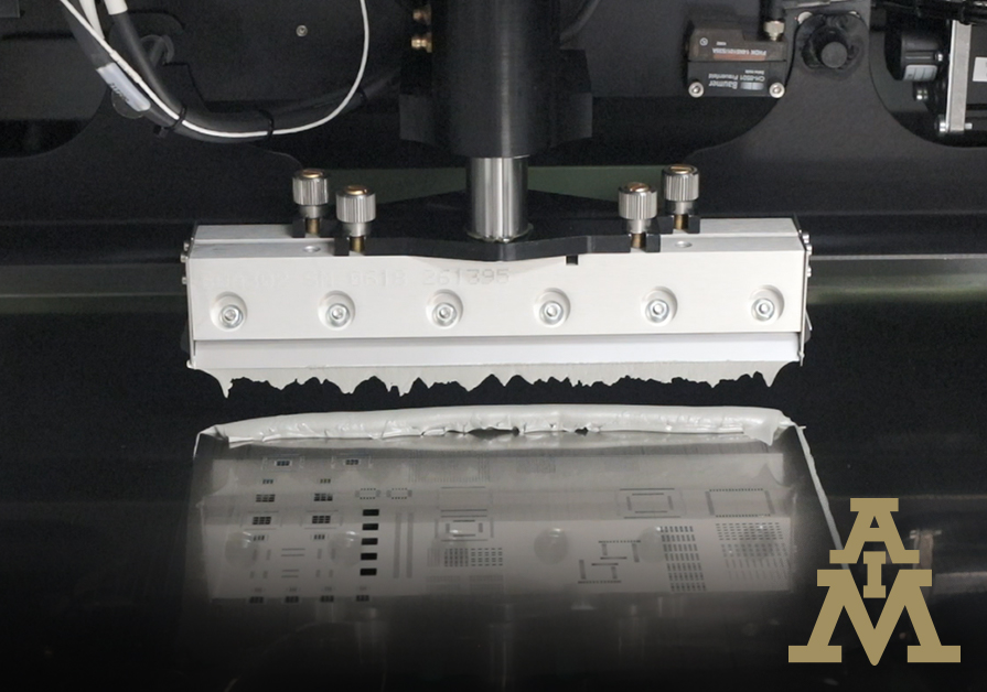
During the print cycle, it is necessary to apply a controlled amount of pressure in an evenly distributed manner across the entire length of the squeegee blade. The purpose of this is to provide the force necessary to push the solder paste across the width of the printable area, filling in all apertures, while wiping the stencil surface clean, leaving behind only a very thin skim coating of solder paste to be seen.
Drawbacks of squeegee pressure
- In the case of rubber or poly squeegee materials, the lower durometer (hardness), blades generally require more downward pressure in order to provide the desired 'clean wipe' of the stencil surface. Herein lies the problem, the more pressure exerted by the squeegee blades, the more gouging or scooping of solder paste out of the stencil apertures occurs. There are two basic fixes to this, you can try printing at a slower print speed, which will enable you to reduce overall squeegee pressure, or upgrade to a harder durometer blade material. For standard PCB assembly, somewhere around 80 to 100 durometer is typical.
- A less visible problem with some types of poly blades is as more downward pressure is applied to the squeegee blade, the poly material will deflect more, much more than a metal blade assembly, which changes the angle of attack between the squeegee blade material and the stencil surface. This can cause problems with paste roll, or the filling of apertures, and solder paste bleed out.
- Another typical problem with using poly blades, is that they will wear very quickly, increasing defect levels as they deteriorate.
- A harder durometer or metal blade squeegee will require less overall pressure than a poly blade, and it is much easier to control solder paste deposition across the length of the blade. A metal blade squeegee will not gouge or scoop the solder paste from stencil apertures, allowing better volume control as well as a better defined solder deposit.
Benefits of squeegee pressure
The key benefits of proper squeegee pressure are more consistent paste height, uniform deposition control, reduced squeegee blade and stencil wear.
Adjustment
To establish proper squeegee pressure for your process, assuming that your squeegee blades are properly installed, and adjusted, start with the following steps.
- Select a good flat substrate.
- Position the substrate to be printed under the stencil.
- Adjust the squeegee pressure so that excess solder will remain across the stencil surface after a print cycle.
- With solder paste applied to the stencil, perform a print cycle.
- Observe the amount of solder paste remaining on the stencil surface
- Add a small amount of squeegee pressure and perform another print cycle.
- Again observe the amount of solder paste remaining on the stencil surface. It should be somewhat less that the first pass.
- Continue to repeat steps 6 & 7 until all that remains visible on the stencil surface is a very thin skim coat of solder paste.
Note
It is key when using poly squeegee blades to use a high enough durometer material to minimize defects during standard processing. Always keep the poly squeegee blade edges straight and sharp.
Some machine manufacturers have available a retrofit kit allowing the change over of poly squeegee blades to metal.
_______________________________________________________
Transporting Solder Paste
-
Solder paste should be shipped on an overnight basis in order to reduce its exposure to environmental conditions. This may be accomplished by land (if possible) or by air. This is especially important during hot/humid weather.
-
International shipments of solder paste should be made as expediently as possible. A transit time of two, three days maximum, is preferable. Solder paste should never be shipped by sea.
-
The inclusion of ice and/or other special packaging materials may be warranted in certain situations, i.e., shipping solder paste during very hot weather; shipping paste internationally; shipping paste of an extremely sensitive composition.
_______________________________________________________
Storing Solder Paste
-
Solder paste should not be allowed to remain on the dock after receipt. Solder paste should be transferred immediately to the proper storage area.
-
Most solder pastes normally have a shelf life of three to six months when stored at room temperature (22°C). Refrigerated: 0°C-12°C (32°F-55°F) / Unrefrigerated < 25°C (< 77°F). Refrigeration will normally double the shelf life of solder paste, while protecting the paste from the varying levels of heat and humidity often found in warehouses and offices.
-
Do not combine new and used solder paste in the same container. This may degrade the new paste.
-
Paste should not be re-refrigerated after the seal has been broken. Any opened material should be resealed and stored at room temperature when not in use. If possible, solder paste should be packaged in quantities no greater than the total daily usage of paste.
_______________________________________________________
Preparing Paste For Use
-
Solder paste should not be used cold.
-
Solder paste should be allowed to reach ambient (room) temperature naturally and completely before breaking the seal of the paste package. DO NOT FORCE WARM THE PASTE. The package of solder paste should be exposed to room temperature for six to eight hours in order to reach ambient temperature. Eight hours (overnight) is recommended for optimal results.
-
Once the solder paste has reached ambient temperature, the seal of the package may be broken. Before applying, paste should be stirred lightly and thoroughly for one to four minutes. Solder paste should be stirred in one direction, either with a spatula (for jars) or with a mixing rod (for cartridges), as per instructions. Stirring the paste ensures an even distribution of any separated material (flux and metal) resulting from storage.
_______________________________________________________
Stencil Application
-
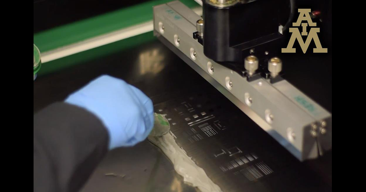
A sufficient amount of solder paste should be applied (by hand or automatic dispenser) to allow for a smooth and even roll during the print cycle. A roll diameter of 3/8 to 1/2 inch (the size of a dime) is normally sufficient for stenciling. The amount of paste applied for the initial application typically should be two or three times the size of the desired roll. This will allow the squeegee blade to "load up" and allow the paste to flow out across the length of the squeegee blade.
-
The length of the roll should correspond to the length of the squeegee blade, which should be slightly larger (1/2 inch on each side) than the board width.
-
Small amounts of fresh solder paste should be applied to the stencil at frequent, controlled intervals. This will help to maintain the paste’s chemistry and workable properties. To best maintain the chemistry of the solder paste, smaller amounts of paste should be added at frequent intervals, rather than large amounts of paste less often.
-
After printing, the SMT process should continue in a timely manner to prevent the solder paste from drying out on the PCB and other time-related problems.
_______________________________________________________
Environmental Conditions
-
For optimal results, the temperature and humidity of the areas in which printing, populating, and reflow take place should be maintained at a stable level. A temperature of 22° - 26°C (72° - 80°F) at 45% ± 5% relative humidity is optimal. Open/Tack times of 24 hours and greater have been achieved at these conditions. In addition, these times have been seen to increase to 48 hours when printed paste has been stored under Nitrogen.
-
Conversely, if temperature and humidity conditions are not maintained at optimal levels, the time that the paste may be exposed to the environment and paste functionality may decrease significantly. Solder paste is also more prone to defects such as slumping, solder balling, and viscosity changes when applied in environments of excessive temperature/humidity.
-
Generally, solder paste will remain functional for the longest periods of time between printing to populating and populating to reflow when temperature and humidity are controlled. When temperature and/or humidity are not controlled, there is a trade-off in the time that the paste remains functional, as well as the functionality of the solder paste.