

By Timothy O’Neill and Karl Seelig
This study evaluates the performance of various types of conformal coating over no clean flux residues left after soldering.
As the demand for smaller, more powerful electronics grows, designers and assemblers face new environmental challenges and unconventional applications never previously considered. At the same time, reducing environmental and health risks associated with electronics manufacturing and disposal has become a priority, prompting a shift in materials and processes used in production.
The need for higher package density and cost reduction has led to the widespread adoption of leadless packages such as QFN, POP, LGA, and Micro-BGA. These components present a significant cleaning challenge, as flux residues often remain trapped under the low-standoff bodies. As a result, many manufacturers now rely on no clean fluxes rather than risk incomplete removal of ionic contamination from difficult-to-reach areas.
At the same time, the need for environmental resistance and tin whisker mitigation has driven increased adoption of conformal coatings. This presents a critical challenge:
- How does no clean flux interact with conformal coatings?
- Can coatings reliably adhere to and protect assemblies with no clean flux residues?
To address these concerns, the AIM Research & Development team partnered with OEM electronics manufacturers and conformal coating suppliers to evaluate the performance of various coating types over different no clean flux residues. This study explores viable flux/coating combinations, helping assemblers balance performance, reliability, and cost.
The Growing Use of Conformal Coating
Conformal coating is increasingly used in PCB design and manufacturing as electronic assemblies are deployed into more diverse and extreme environments. Many of these applications would have been considered unsuitable for electronics just a few years ago. Some key benefits of conformal coating include:
- Environmental contaminant protection, such as from moisture, dust, and chemicals.
- Reduction of tin whisker formation, a critical factor in lead-free assemblies.
- Prevention of electrical shorts due to contaminants.
While conformal coating suppliers recommend cleaning before application, many manufacturers choose to coat directly over no clean residues to avoid:
- High cleaning costs.
- Production delays due to cleaning steps.
- The risk of incomplete flux removal under low-standoff components.
However, applying conformal coating over unremoved no clean flux residues raises concerns regarding adhesion, reliability, and long-term performance.
Study Overview and Testing Methodology
Objectives
This study evaluated the compatibility of conformal coatings with no clean flux residues by assessing electrical performance, adhesion strength, and environmental durability. To ensure a thorough evaluation, the following industry standards were used:
- IPC J-STD-004 – SIR Testing (Surface Insulation Resistance).
- IPC CC-830 – Electrical Insulating Compound Performance Qualification.
- ASTM D3359 – Adhesion Tape Test.
These tests measured SIR values, adhesion properties, and environmental durability of each material combination. Results were compared to supplier-provided baseline data to determine if performance was enhanced or degraded when combining flux residues with conformal coatings..
Types of Conformal Coatings Evaluated
The following five classes of conformal coatings were tested over different no clean flux residues:
Acrylics
Thermoplastics dissolved in solvents
| Strengths | Weaknesses |
| Air Dry | VOC Bearing Solvents |
| Easy Solvent Rework | Poor Solvent Resistance |
| Good Moisture Barrier | Flammable |
| Ease of Use | Softens in High Temp |
…
Urethanes
Chemically cured cross-linked polymers
| Strengths | Weaknesses |
| Solvent Resistant | Some contain VOCs |
| Humidity Resistant | Rework |
| Abrasion Resistant | Cure rate environmentally dependent |
| Dielectric Properties | Worker health risks |
…
Silicones
Moisture-cured coatings
| Strengths | Weaknesses |
| Humidity Resistant | Abrasion |
| Moisture Resistant | Workplace contamination |
| Flexibility | |
| Temperature Tolerant |
…
Epoxies
Typically two-part systems with high chemical resistance
| Strengths | Weaknesses |
| Humidity Resistant | Two-Part |
| Moisture Resistant | Rework |
| Abrasion Resistant | Pot life |
| Dielectric Properties |
…
Acrylated Urethanes
UV-curable urethane coatings
| Strengths | Weaknesses |
| Protective Properties | Capital Investment |
| Through Put | Rework |
| Environment Impact | Shadowing |
| UV Inspection |
…
Results and Key Findings
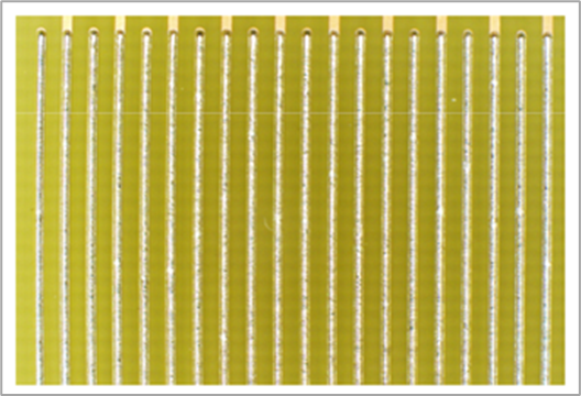
Surface Insulation Resistance (SIR) Testing
The SIR pass/fail criteria (IPC J-STD-004B §3.4.1.4.1) are as follows:
- Minimum insulation resistance: ≥100 MΩ.
- No electrochemical migration reducing conductor spacing by >20%.
- No corrosion of conductors.
Test results summary for all combinations tested:
- All flux/coating combinations exceeded SIR requirements.
- No dendrite formation was observed.
- No measurable reduction in conductor spacing.
- No discoloration between conductors
- No water spots present
- No presence of subsurface migration
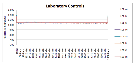
The following graphs show examples of typical SIR results observed.
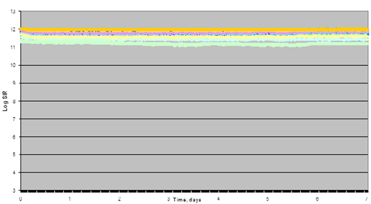
Graph 1. “L” UV Cure Coated, “Paste 54” (Sn-Pb), “Control”
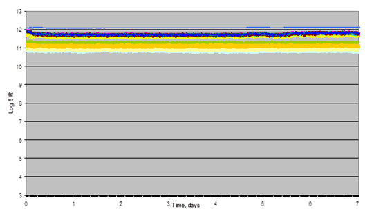
Graph 2. “H” UV Cure Coated, “Paste 54” (SAC305), Control
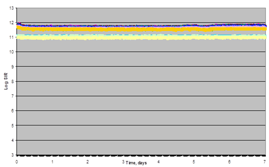
Graph 3. “H” UV Cure Coated, “Paste 54” (Sn-Pb), Control
Thermal Shock and Adhesion Testing
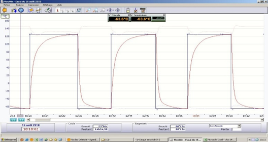
To evaluate the durability of conformal coatings over no clean flux residues, thermal shock testing was conducted with temperature cycling between -60°C and +125°C. The initial assumption was that failures might be caused by softening of the flux residue at high temperatures, allowing for movement between the coating and PCB. However, further examination revealed a different failure mode—cohesive failure within the flux residue itself.
In these cases, the flux residue remained strongly adhered to both the PCB and the conformal coating, but internal cracking developed within the residue, leading to delamination. This failure mode was observed in all coatings except silicone-based materials, which remained intact. UV-cured conformal coatings exhibited the worst performance, with widespread delamination, while solvent-based acrylic coatings performed better but still showed signs of failure. The results indicated that a coating’s ability to accommodate mechanical stress was a key factor in preventing delamination.
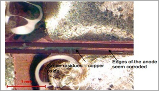
Photo evidence of delaminated samples confirmed the cohesive failure within the flux residue rather than detachment from the PCB or coating. Figure 1 illustrates how the flux remained adhered to the PCB even after the coating detached.
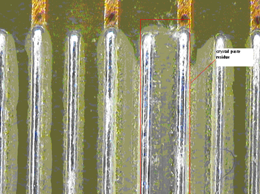
While delamination was clearly observed, it remained undetermined whether a delaminated but contiguous conformal coating could still provide adequate environmental protection. Further studies would be needed to assess whether coatings that separate but remain in place still act as effective barriers against moisture and contamination.
The Role of Coating Modulus in Cold Temperature Performance
Further analysis revealed a strong correlation between a coating’s modulus (stiffness) and its performance under cold temperature cycling.
Coatings with a high modulus, such as UV-cured urethanes, were significantly more prone to delamination due to the mismatch in the coefficients of thermal expansion (CTE) between the rigid flux residue and the coating material. In contrast, coatings with a low modulus, such as silicone-based materials, provided the necessary flexibility to accommodate temperature fluctuations without causing stress fractures in the flux residue.
Since solder paste flux residues are typically resin-based, they become rigid after reflow. As temperatures drop, these residues become even more brittle, making them more susceptible to cracking when paired with a stiff conformal coating.
To test this theory, different flux and coating combinations were evaluated, including a high-modulus UV-curable urethane versus a low-modulus UV-curable silicone, as well as a resin-based solder paste with a hard post-reflow residue versus a paste with a softer, waxy residue. The results confirmed that reducing the modulus of either the coating or the residue significantly reduced delamination failures.
Further observations indicated that solvent-based acrylic coatings outperformed UV-cured urethanes, possibly due to the ability of the solvent to facilitate a more intimate bond with the residue. This closer bond appeared to lessen the adverse effects of CTE mismatch and improved overall adhesion.
The data collected from these tests is summarized in Figure 2 and Table 6 which illustrate how different coatings performed under extreme thermal conditions. Note, Tg is glass transition and higher Tg means more rigid.
| UV Curable Urethane Hybrids | Tg | Paste A | Paste B | Paste C | Comment |
| A | 40 | 1 | 1 | 1 | Complete delamination, combination with Paste C was the worst |
| B | 25 | 3 | 1 | 4 | Delamination but not global |
| C | 3 | 4 | 3 | 4 | Wetting issues, slight delamination |
| D | -60 | 5 | 5 | 5 | Perfect, no delamination |
Minimum Temperature Threshold for No Clean Pastes
An additional test was conducted to determine the lowest temperature at which a resin-based no clean paste could be paired with an acrylic or acrylate/urethane coating before suffering delamination. Results were inconsistent across different materials, but none of the tested flux/coating combinations withstood more than -35°C for 10 cycles before exhibiting delamination.
This suggests that applications requiring extreme cold temperature reliability must carefully select conformal coatings with low modulus characteristics to prevent mechanical stress fractures within the flux residue.
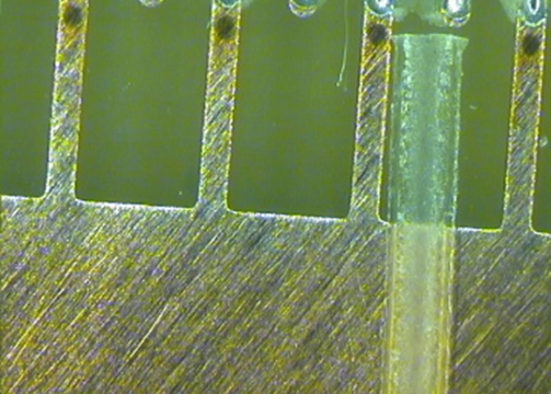
Figure 3 and Figure 4 illustrate the test setup. Figure 5 shows an example of a failed sample.
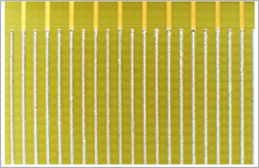
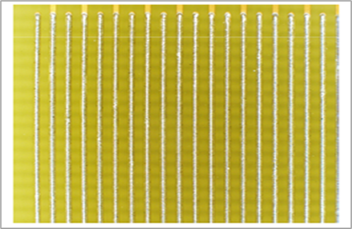
Interestingly, when a low/no residue nitrogen reflow solder paste was used, no delamination occurred during thermal shock testing. This suggests that the absence of a rigid flux residue eliminates the primary failure mechanism observed in resin-based solder pastes. The contrast between the previous traditional no clean paste results and the low/no residue solder pastes results can be noted in Figure 6 and Figure 7.
Hard Flux Residue and Urethane Coating Delamination
Additional visual analysis of delaminated samples provided further evidence of the role that flux residue plays in coating failure. A series of images illustrate the specific interaction between hard flux residues and high-modulus urethane coatings, highlighting the cracking and detachment issues observed in these materials:
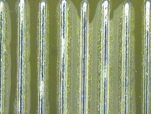
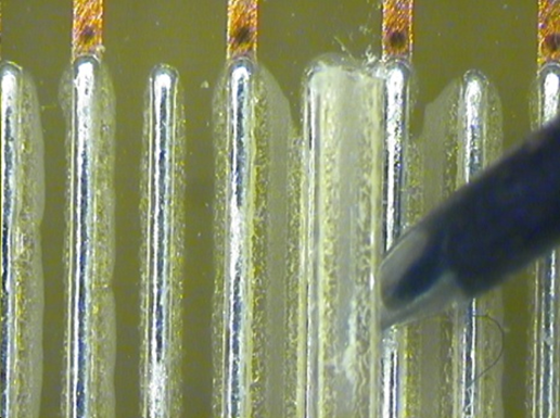
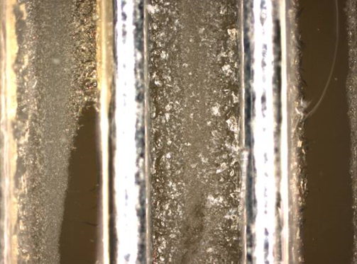
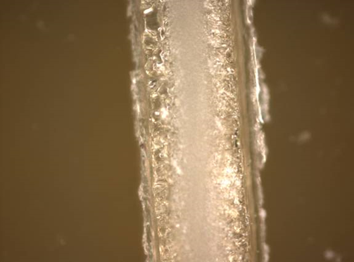
These findings reinforce the conclusion that flux residues with high rigidity after reflow are highly susceptible to fracture when paired with stiff conformal coatings.
Moisture Absorption and Electrical Failures
While conformal coatings provide environmental protection, they are not hermetic. The study found that all tested coatings exhibited varying degrees of moisture vapor transmission, which can become a critical factor in long-term electrical reliability.
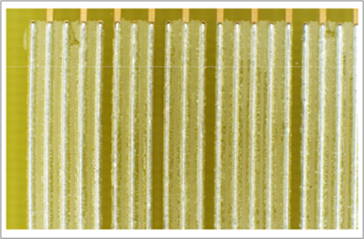
In cases where softer flux residues were used, moisture absorption within the residue led to corrosion and dendrite growth, significantly increasing the risk of electrical failures. Surface Insulation Resistance (SIR) testing at 85°C/85% RH revealed that some material sets were particularly vulnerable to dendrite formation, while those tested at 40°C/90% RH showed fewer failures.
The data collected during SIR testing is summarized in Figure 13. Further confirmation of moisture-related failures was observed in Figure 14, which shows dendrite growth developing under humid test conditions.
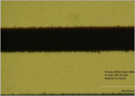
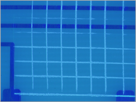
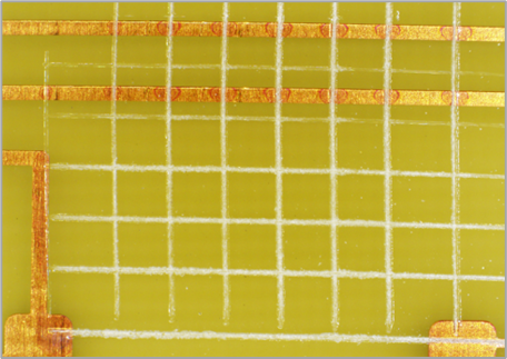
Adhesion Testing via Crosshatch and Tape Test
To further evaluate coating performance, adhesion testing was conducted using a crosshatch cut and tape pull-off test under both black light and white light conditions. Results confirmed that most coating/flux combinations demonstrated acceptable adhesion, with black light examination revealing uniform adhesion in most cases.
Final adhesion results are presented in Figure 15 and Figure 16, which visually confirm proper coating adhesion across tested samples.
Conclusion and Industry Implications
This study represents hundreds of individual tests conducted to evaluate the interaction between conformal coatings and no clean flux residues.
While the potential combinations of coatings and residues are too numerous to test exhaustively, key insights were extracted to provide practical guidance for manufacturers considering this approach.
Key Takeaways:
- Conformal coatings can be successfully applied over no clean flux residues, but compatibility testing is essential.
- Softer coatings (silicones) resist delamination best, while harder coatings (UV-cured urethanes) increase delamination risk at cold temperatures.
- Flux residue characteristics matter—softer residues prevent delamination but can compromise SIR performance.
- Moisture absorption remains a challenge—increasing the risk of dendritic growth and electrical failure.
- The shift toward no clean processes will continue, especially as RoHS exemptions expire and tin whisker mitigation remains a priority.
Final Thought
As electronics assemblies grow more complex, the ability to effectively coat over no clean flux residues will become increasingly important for reliability and cost control. Understanding the interplay between coatings, flux residues, and environmental factors is essential for long-term success in mission-critical applications.